Home › Unlabelled ›
Reading Electrical Schematics Drawings : Electrical Plan Reading - Wiring Diagram & Schemas - We will write an article regarding the standard practices to follow while drawing circuit diagrams.
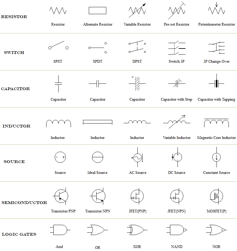
Reading Electrical Schematics Drawings : Electrical Plan Reading - Wiring Diagram & Schemas - We will write an article regarding the standard practices to follow while drawing circuit diagrams.. Understanding how to read and follow schematics is an important skill for any electronics engineer. Well there are some standard practices that you have to keep in mind while you draw. Course reading electrical drawings, schematics, and blueprints schematic diagrams and blueprints are vital for both the planning and installation phases of a residential electrician's work. Reading schematics is just a matter of recognizing the symbols and see how they connect. To read and interpret electrical diagrams and schematics, the basic symbols and conventions used in the drawing must be understood.
There are other equally important types of drawings that are not the subject of this article including logic diagrams, data tables and single line diagrams, wiring diagrams, data communication. Well there are some standard practices that you have to keep in mind while you draw. Potential sheet to sheet cross referencing. Heating, cooling shows how electricity gets through switches and to loads. Schematic comprehension is a pretty basic electronics skill, but there are a few things you should know before you read this tutorial.
how to read electrical drawing and diagram in hindi | YK ... from i.ytimg.com We will write an article regarding the standard practices to follow while drawing circuit diagrams. One of the first steps in reading an electrical schematic is understanding the different symbols used to represent system components, or at least having access to a schematic symbol. Circuit layouts and schematic diagrams are a simple and effective way of showing pictorially the electrical. An electrical schematic is a logical representation of the physical connections and layout of an electric a title block is the border and text of the drawing that describes the project and current sheet. This article concentrates on how electrical components are represented on diagrams and schematics. While schematics require some basic knowledge of electrical hardware, you can gain a lot of new insights into your home or property by. Start drawing lines by clicking on the draw lines tool in the smartpanel. This concise book describes how reading a schematic is like looking at a map and is similar to reading a map, and how to approach it that way.
Schematics produced in a professional cad package.
Learn to read electrical and electronic circuit diagrams or schematics. However, electrical drawings contain a complex set of symbols and interconnection notation that can be difficult to. Start drawing lines by clicking on the draw lines tool in the smartpanel. On a schematic you will also see a electrical components symbol next to it will have a identification number next to its abbreviation (ie. Heating, cooling shows how electricity gets through switches and to loads. An electrical schematic is a logical representation of the physical connections and layout of an electric a title block is the border and text of the drawing that describes the project and current sheet. Design engineers and technicians use schematics to build and troubleshoot complex circuits, while plant operators use knowing how to read and interpret various types of electrical drawings are an essential skill that all electrical workers must posses to effectively carry out their tasks. Electrical symbols & electronic symbols. These electrical schematic symbols will help you to identify parts when working with an electrical schematic. I would recommend a book, beginner's guide to reading schematics by robert traister and anna lisk. A schematic in electronics is a drawing representing a circuit. By default, you'll draw a segmented line with an arrow at one end. The most basic symbol is a simple thus, electrical flow of charge is from negative to positive in a wire.
Other types of lines represent cables, logical an electronic circuit has many electrical highways and byways. While schematics require some basic knowledge of electrical hardware, you can gain a lot of new insights into your home or property by. However, electrical drawings contain a complex set of symbols and interconnection notation that can be difficult to understand. Among these you'll find commonly used electrical drawings and schematics, like circuit diagrams, wiring diagrams, electrical plans and block diagrams. .will talk about how to read a schematic and how to identify electrical components on a pcb (printed circuit board).electrical components are identified two main ways.
Schematic Wiring Diagram Symbols | Wiring Diagram from www.edrawsoft.com With rare exceptions, schematics should be read left to right. I would recommend a book, beginner's guide to reading schematics by robert traister and anna lisk. Read schematics in the pattern that you would read the text. These electrical schematic symbols will help you to identify parts when working with an electrical schematic. Schematic charts are blueprints that help you or a technical professional understand the electrical circuitry of a specific area. Well there are some standard practices that you have to keep in mind while you draw. A ladder schematic is a drawing intended for tracing specific circuits. Once you know how to read an electrical schematic, the next step is to design your own.
Electrical symbols & electronic symbols.
An electronic schematic is a diagram that uses standardized electronic and electrical symbols to generally, schematics are laid out to read like text in a book. We will write an article regarding the standard practices to follow while drawing circuit diagrams. The reason for this is to make the drawing simpler. In this course, you can learn how to read a instructor christopher randall also explains how to read wiring diagrams and schematics, as well as ladder diagrams specifying the. However, electrical drawings contain a complex set of symbols and interconnection notation that can be difficult to understand. Electrical symbols & electronic symbols. These electrical schematic symbols will help you to identify parts when working with an electrical schematic. How to follow an electrical panel wiring diagram. I would recommend a book, beginner's guide to reading schematics by robert traister and anna lisk. By default, you'll draw a segmented line with an arrow at one end. While schematics require some basic knowledge of electrical hardware, you can gain a lot of new insights into your home or property by. Learn to read electrical and electronic circuit diagrams or schematics. Heating, cooling shows how electricity gets through switches and to loads.
Electrical basics sample drawing index. A schematic you find on the internet sometimes includes only electronic components and no connectors. By default, you'll draw a segmented line with an arrow at one end. A schematic in electronics is a drawing representing a circuit. This article concentrates on how electrical components are represented on diagrams and schematics.
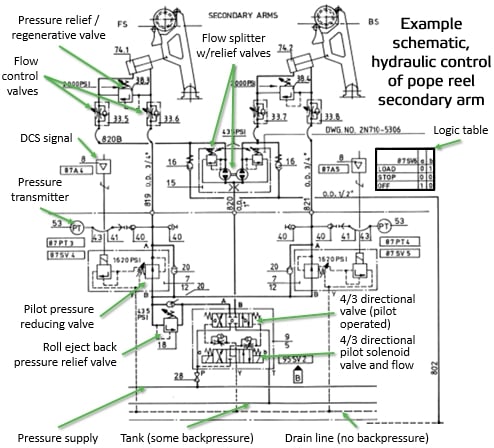
How To Read Hydraulic Schematic Drawings - Wiring Diagram from www.valmet.com Start drawing lines by clicking on the draw lines tool in the smartpanel. Read schematics in the pattern that you would read the text. One of the first steps in reading an electrical schematic is understanding the different symbols used to represent system components, or at least having access to a schematic symbol. Electronics symbols for schematics and wiring diagrams are mostly universal with a few of the symbols that may look different if reading other types of schematics. This article concentrates on how electrical components are represented on diagrams and schematics. Schematics produced in a professional cad package. A schematic you find on the internet sometimes includes only electronic components and no connectors. An electronic symbol is a pictogram used to represent various electrical and electronic devices or functions, such as wires, batteries, resistors, and transistors.
Trace through sequence of operation using ladder diagrams:
Schematic comprehension is a pretty basic electronics skill, but there are a few things you should know before you read this tutorial. Understanding how to read and follow schematics is an important skill for any electronics engineer. The most basic symbol is a simple thus, electrical flow of charge is from negative to positive in a wire. However, electrical drawings contain a complex set of symbols and interconnection notation that can be difficult to understand. Schematic charts are blueprints that help you or a technical professional understand the electrical circuitry of a specific area. Likewise, an electronic schematic drawing uses a plain, straight line to indicate a standard conductor; One of the first steps in reading an electrical schematic is understanding the different symbols used to represent system components, or at least having access to a schematic symbol. Circuit layouts and schematic diagrams are a simple and effective way of showing pictorially the electrical. Potential sheet to sheet cross referencing. With rare exceptions, schematics should be read left to right. By default, you'll draw a segmented line with an arrow at one end. A schematic you find on the internet sometimes includes only electronic components and no connectors. The problem with the symbol is that the cathode, not the anode, is the negative side.